Level gauges radar waveguide D- 6

Level gauges radar waveguide D- 6

Purpose

Level gauges radar waveguide D-6 (further – level gauges) are intended For continuous measurements level liquids And loose​ avg.

Region applications

Level gauges wide are used V composition technological installations in various industries :

  • chemical industry;
  • atomic industry;
  • metallurgical industry;
  • mining and processing industry;
  • pharmaceutical industry;
  • food industry;
  • pulp and paper
waveguide-1

Peculiarities level gauges D-6

  • high-precision And continuous measurement level liquids And syp – sneeze Wednesday;
  • level gauges Not are subject to influence changes parameters measured environment , such as: temperature, pressure, density, viscosity .
  • measurement level V various, complex conditions operation: high temperature, high pressure, low meaning dielectric​ constant measurable Wednesday, corrosive

Design And principle actions

The operating principle of level meters is based on the use of time-resolved reflectometry (TDR) technology. The emitter of the level meter generates an electromagnetic pulse that propagates along measuring waveguide module (further – probe), immersed in the measured medium. When the pulse reaches the surface of the measured Wednesday, He reflected from her surfaces And comes back V receiver level gauge. Calculator level gauge processes received signal, measuring temporal interval between moment – volume dispatches generated impulse And moment reception reflected pulse , and calculates the level of the measured (controlled) environment.

Converters temperatures A- 2

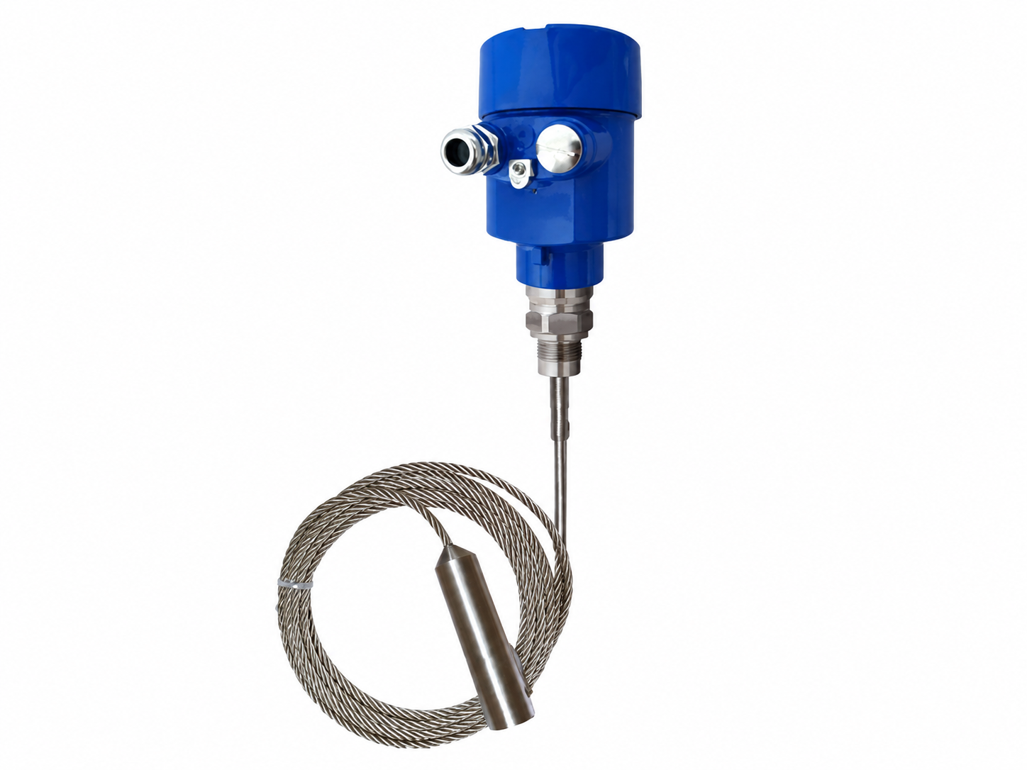
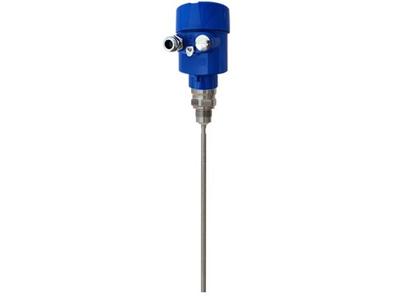
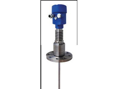
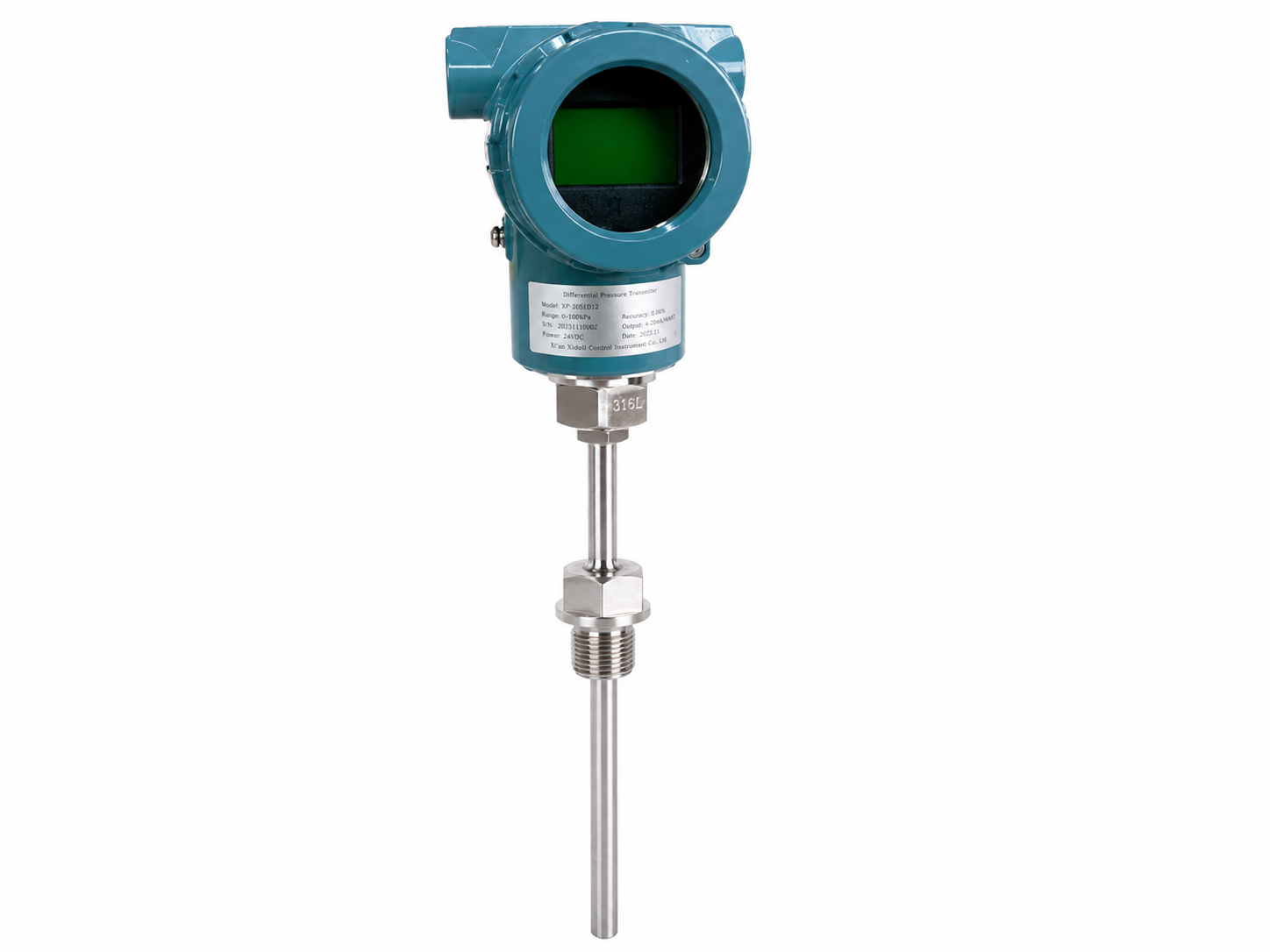
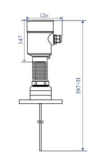
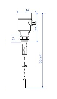
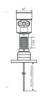
The level gauges consist of an electronic unit housed inside a metal housing and a probe. Depending on the modification, the level gauge housing can be made of aluminum alloy or stainless steel . steel. Probe Maybe have different design: Cable , rod, coaxial. Probes are made from various materials , taking into account process parameters: aggressiveness of the medium, temperature , pressure. The length of the probe structurally determines the measurement range . level. By type accession level gauges can be presented V threaded or flanged execution. Level gauges can additionally be equipped liquid crystal display. Level gauge capable issue measured meaning V view analog​ current 4~20 mA or V view digital values By protocol HART and transmit it for further use by the control system, such How distributed system management (RSU) or programmable logical controller (PLC).

Technical characteristics

Name characteristics Meaning
Measurable Wednesday liquid, bulk materials
Types probes rod cable
Range measurements from 150 to 6000 mm (rod probe) from 150 to 14000 mm (cable probe)
Limits permissible basic absolute error measurements level ±3.1 mm (at distance to measurable surfaces up to 10,000 mm)±4.2 (at distance to measurable surfaces over 10,000 mm)
Limits permissible additional absolute errors measurement level caused by change temperatures surrounding​ air on every 10 °C from +20 °C ±0.28 mm
Range temperatures measurable Wednesday -40…+350 °C
Range pressure measurable Wednesday -0.1…4.0 MPa
Day off signal analog 4-20 mA digital HART
Nominal voltage power supply 20…28 IN permanent current
Consumed power Not more 660 mW
Accession To process threaded flange
Material corps aluminum stainless steel alloy steel 304
Material probe Stainless steel steel 304 Fluoroplastic-4 – PTFE
Conditions operation:
– temperature surrounding Wednesday
– relative humidity
– atmospheric pressure
from -40 to +70 °C
from 0 to 90 %
from 84 to 106.7 kPa
Appointed term services 15 years
Average development on refusal – Not less 63000 h

Overall dimensions dimensions, mm

Code Description
4 Type weekend signal/voltage nutrition
2 Analog 4-20 mA / 24 IN permanent current
3 Analog 4-20 mA + HART / 24 IN permanent current
5 Range temperatures measurable Wednesday
1 Standard temperature execution (-40…+130 °C)
3 Extended temperature execution (-40…+250 °C)
4 High temperature temperature execution (-40…+350 °C)
6 Range pressure measurable Wednesday
1 -0.1…0.3 MPa
2 -0.1…2.0 MPa
3 -0.1…4.0 MPa
X Special accession (type required indicate separately)
7 Material seals
V Viton (fluororubber)
TO Kalrez ( perfluororubber )
X Special execution (type required indicate separately)
8 Material corpora/degree protection
A Frame from aluminum alloy/IP67
S Frame made of stainless steel 304/IP67
X Special execution (type required indicate separately)
9 Execution By explosion protection
O Without explosion protection (standard performance)
Exi Marking explosion protection 0Ex ia IIC T1…T6 Ga X
10 Accession under cable input
N Hole under cable input ½” NPT
M Hole under cable input M20
11 Availability residential complex display
0 Without residential complex display
A WITH residential complex display
12 Length waveguide
XXXX Length waveguide V mm.
13 Verification
Factory calibration
PV Primary verification
Order example D-6-AA-3-1-3-V- A – Exi – M -A-10000- PV