Flow meters With increased precision

Flow meters With increased precision

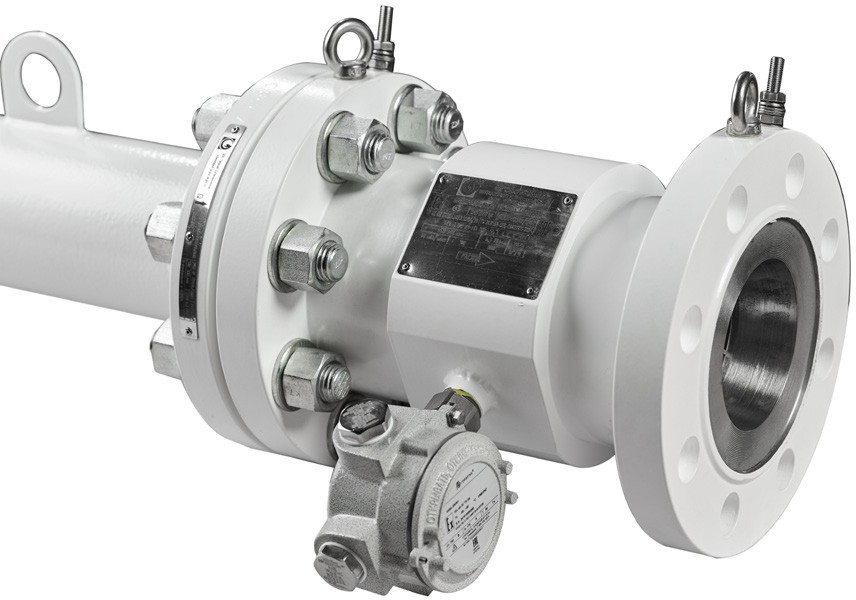
Flow Meters with Increased Precision

TPR GT provides commercial and technological metering for liquids with varying density and viscosity.

  • TPR GT: range measurements 10:1.
  • TPR GT cover wide range from 0.3 to 150 cSt.

Pressure Drop

Pressure drop in turbine converters consumption GT depends on the density of the measured liquid, its kinematic viscosity And current consumption. For calculation difference pressure the following is used formula:
Pback ≥ 2 × ΔP + 1.25 × Pv
Where:
ΔP = 25 × d × ν0.2 × (Q / Qmax)2

The pressure drop across the flow meter is determined by:
Where:

  • ΔP — pressure drop across the flow meter, kPa
  • d — specific density
  • ν — kinematic viscosity of the liquid, mm²/s (cSt)
  • Q — actual flow rate, m³/h
  • Qmax — maximum standardized flow rate of the flow meter, m³/h

Specific gravity is calculated as the ratio of the density of the working liquid (kg/m³) to the density of the reference substance (1000 kg/m³).

Flow meters With increased precision

Back Pressure

For liquids other than liquefied gases, the minimum absolute back pressure is calculated from the inequality above to prevent cavitation.

  • ΔP — pressure drop of the flow meter at maximum flow rate (including flow straightener)
  • Pv — vapor pressure of the liquid at the measurement temperature

Typical Installation Scheme for GT Turbine Flow Converters

Required lengths of straight pipeline sections before and after turbine converters consumption are an important condition for ensuring the accuracy of flow measurements. Optimal length direct section allows to stabilize the flow of the medium, minimizes the influence of local resistances and reduces error measurements.

Recommended values lengths depend depending on the type of flow And designs himself flow meter.

flow-meter

Metric system units

Nominal size, inch Nominal size, mm Model number GT Flow (m³/h)¹ Min. Flow rate (m³/h)¹ Max. Installation length, mm Weight (kg), with flanges² ANSI 150 Weight (kg), with flanges² ANSI 300 Weight (kg), with flanges² ANSI 600
1 25 GT 01 0.5 15 140 8 9 10
1.5 40 GT 015 3.4 36.4 165 12 14 15.5
2 50 GT 02 6 64 165 15 16.5 19
3 80 GT 03 15 160 254 25 29 33
4 100 GT 04 30 320 305 38 51 63
6 150 GT 06 60 640 356 42 59 83
8 200 GT 08 120 1280 406 74 98 139
10 250 GT 10 200 2140 508 108 147 224
12 300 GT 12 300 3210 610 182 234 304
16 400 GT 16 400 4280 813 289 392 489
18 450 GT 18 500 5885 914 385
20 500 GT 20 600 6420 1016 460 620

Specification

Chapter Parameter Meaning
Surrounding Wednesday Range temperatures surroundingWednesday from -50 °C to +60 °C
Range temperatures working

liquids

from -40 °C to +150 °C
Temperature storage -50 to +50 °C
Climate protection IP66/67
Safety Explosion protection 1Ex db IIC T6…T3 Gb X
 

Mechanics

Size counter 1″ to 20″ (25 to 500 mm)
Pressure range to 25.0 MPa
 

Material corps counter

Carbonaceous, cold-resistant or corrosion-resistant steel (A106/ A105, A333Gr6, 316L, 12X18H10T)
Material flanges A106, A350LF2, 316L , 12X18H10T
Material rotor AMg5 (easy alloy), titanium alloy, corrosion-resistant steel
Material bearings alloy carbide tungsten


Technical characteristics

Accuracy ±0.10 %; ±0.15 %
Repeatability 0.02
Flow range 0.5 to 6420 m³/h
Viscosity range to 150 sSt , By order to 1500 sSt