Converters Pressure D – 3

Converters Pressure D – 3

Converters Pressure D – 3

Purpose

Converters pressure D-3 (hereinafter – converters) intended​ For continuous measurements absolute pressure, from excess pressure, pressure discharge, differential pressure​ And transformations measured values V unified day off signal permanent current 4-20 mA And digital day off signal​ on base HART protocol. Converters intended For measurements​ pressure

Region applications

Pressure transducers are used in automatic control systems, regulation And management technological processes V various industries industry.

Converters pressure D - 3
Principle actions

Principle actions converters founded on use dependencies​ between measurable pressure And elastic deformation of the sensitive element. A membrane is used as a sensitive element , which mechanically acts on the dielectric , on which posted strain-sensitive semiconductor circuit from four silicon strain gauges , united V Wheatstone bridge . The pressure of the measured medium is transmitted through the separating membrane And filling liquid on sensitive element, causing at this deformation sensitive element And change​ values electric resistance strain gauges Wheatstone Bridge . Difference potentials on exit bridge Wheatstone depends from the current pressure. The converter electronics processes the received changes resistance And transforms V unified current day off signal 4-20 mA or V digital signal on base HART protocol . To display information, converters are optionally can be equipped residential complex display.

The converter consists of a sensor module and an electronic unit. Sensor module consists of from measuring block And boards analog- digital converter (ADC).

Sensor With remote membrane

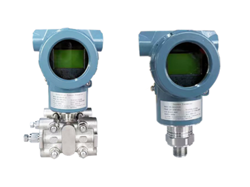
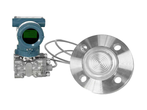
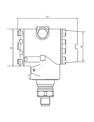
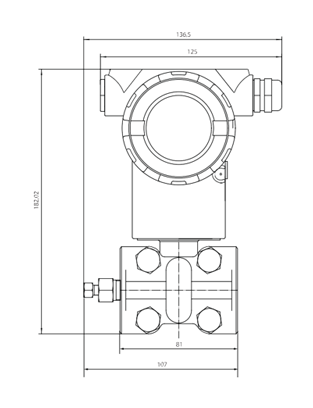
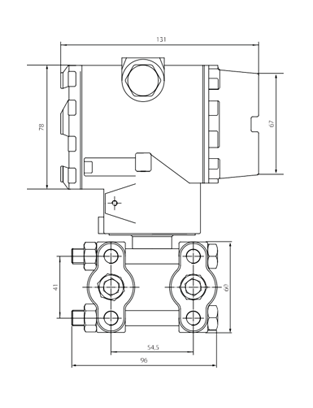
Converters can be manufactured V nipple or flanged versions.

In nipple-type converters, the measuring unit consists of from dividing membranes And sensitive element, the space between them is filled with a separating liquid ( silico – new oil).

IN converters flanged execution measuring block consists of from dividing membranes with sides high pressure and dividing membranes with sides low pressure. The cavity between membranes filled dividing liquid ( silicone – howl oil). Sensitive element posted inside closed cavity filled with separating liquid. The measuring unit also has protective membrane from reloading pressure.

Frame electronic block consists of from two sections, hermetically sealed isolated from each other. One section contains the terminal block, the other contains the electronics board and LCD display. The electronics housing is closed lids With seals.

Main technical characteristics

Name characteristics Meaning
Measurable Wednesday liquid, gas, steam
Converter D-3-G Converter D-3-A Converter D-3- D measurement excess pressure measurement absolute pressure measurement differential pressure
Range measurements, kPa
–  Converter D-3- G
–  Converter D-3- A
–  Converter D-3- D
 
from -100 to 60000
from 0 to 3000
from -500 to 2000
Range temperatures measurable Wednesday, °C from -40 to +120
Day off signal from 4 to 20 mA;
from 4 to 20 mA + HART
Voltage nutrition (constant current), IN from 12 to 42
Conditions operation:
–  temperature surrounding Wednesday, °C
–  relative humidity air, %
–  atmospheric pressure, kPa
from -40 to +85 1)
from 0 to 100
from 84 to 106.7
Average term services, years 12
Average development on refusal, h 75,000
  • Performance display provided V range from -30 to +65 °C

Ranges measurements converters

Model KDI 1) Range dimensions 2) Tuning range Overload pressure
D-3- G 0 from -6 to 6 kPa from 0.6 to 6 kPa 200 kPa
1 from -40 to 40 kPa from 2 to 40 kPa 1000 kPa
2 from -100 to 250 kPa from 2.5 to 250 kPa 4000 kPa
3 from -100 to 6000 kPa from 60 to 6000 kPa 18,000 kPa
4 from -100 to 10000 kPa from 100 to 10000 kPa 20,000 kPa
5 from -100 to 21000 kPa from 210 to 21000 kPa 40,000 kPa
6 from -100 to 40,000 kPa from 400 to 40,000 kPa 50,000 kPa
7 from -100 to 60000 kPa from 600 to 60000 kPa 70,000 kPa
D-3- A 0 from 0 to 40 kPa from 2 to 40 kPa 100 kPa
1 from 0 to 250 kPa from 2.5 to 250 kPa 400 kPa
2 from 0 to 3000 kPa from 30 to 3000 kPa 5000 kPa
D-3- D 0 from 0 to ±1 kPa from 0.1 to 1 kPa 40 kPa
1 from 0 to ±6 kPa from 0.2 to 6 kPa 100 kPa
2 from 0 to ±40 kPa from 0.4 to 40 kPa 200 kPa
3 from 0 to ±250 kPa from 2.5 to 250 kPa 800 kPa
4 from -500 to 2000 kPa from 20 to 2000 kPa 4000 kPa
  • Code range measurements.
  • Specified range measurements Maybe be expressed V others units measurements pressure: Pa, MPa, mbar , bar, m water. Art., mm water. Art., mm rt Art., kgf/cm 2 , atm

Metrological characteristics

Name characteristics Meaning
Range measurements (DI) 1) , kPa
–  Converter D-3- G
–  Converter D-3- A
–  Converter D-3- D
 
from -100 to 60000
from 0 to 3000
from -500 to 2000
Limits permissible basic given errors To measurement range , % ±0.075 at 1 ≤ TD 2) ≤ 10,
±(0.075·TD 2) ) at TD 2) >10;
Limits permissible additional errors measurements from change temperatures surrounding Wednesday from normal conditions​ V range workers temperatures, on every 10 ºС ± ((0.024 % from VPI 3) +
+0.045 % from DI 3) ) / 2.8)
Limits permissible additional given errors to range measurements from changes voltage nutrition from normal​ conditions V range workers conditions, on every 1 IN, % ±0.005
  • Specified range measurements from lower limit measurements (NPI) to top limit measurements ( VPI ), a specific measurement range in accordance with the table “measurement ranges of converters”.
  • TD – coefficient reconfiguration range measurements, is calculated How attitude maximum top limit measurements To range measurements after reconfiguration V in accordance With table “ranges measurements converters.”
  • IN case reconfiguration range measurements they’re setting up VPI to reconfigurations, A DI after.

Overall dimensions dimensions, mm

dimensions
dimensions
dimensions
dimensions